
Given today’s economic pressures and renewed focus on the environment, paint finishers are looking more closely than ever at alternate technologies and processes to achieve a sustainable painting operation. This has particularly been true for automobile paint finishers, where over the past decade new strategies and technologies have been developed to improve efficiency and flexibility, reduce capital and operating costs and minimize environmental impact of the paint shop, while at the same time delivering a world class paint finish.
Now, a trend is developing within the aerospace paint finishing industry in which aircraft manufacturers are beginning to adopt strategies developed and proven by automotive paint finishers to improve quality and reduce operating costs of their paint finishing facilities.
As an example, an aircraft manufacturer is constructing a new facility to build jets designed for executives. The company wanted to adopt paint hangar (spray booth) design strategies that would improve their paint finish quality to produce a “showroom-type” appearance. To assist in this task, the company contracted Dürr Systems, Inc., a supplier of turnkey paint finishing systems, to draw upon Dürr’s vast experience of designing paint finishing systems for the automotive industry. Specifically, the manufacturer was looking to utilize spray booth design techniques and strategies commonly used in the design of an automotive paint booth to improve coating appearance of their aircraft while also minimizing energy usage and overall environmental footprint of their new paint facility.
The purpose of the paint hangar is to provide a ventilated, clean, tempered space for the spray application of a coating. ventilation air needs to be provided to remove hazardous vapors and paint particulate overspray. In addition, it is important that the ventilation air flows evenly around the aircraft in order to achieve a high finish quality. Typically, a paint hanger for small jets would utilize a “cross-draft” style design in which ventilation air is supplied across the nose and down the length of the aircraft. The air is then extracted from the paint hangar at some distance behind the aircraft. This is an efficient paint hangar design with respect to energy usage (relatively low air flow rates required). However, a common problem with this design is “dry-spray”—paint overspray from the forward portion of the aircraft which is carried by the cross-draft air flow to the aft section of the aircraft which causes a gritty, bumpy surface appearance. This type of surface defect was unacceptable for the executive jets to be produced in their new facility.
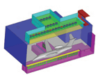
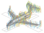
To reduce the possibility of a dry-spray appearance defect, the company wanted to use a down-draft style paint hangar, similar to that of an automotive paint spray booth. With a down-draft style design, paint overspray is carried downward and away from the aircraft, thus eliminating the dry-spray issue and providing for a smoother coating appearance. However, as compared to a cross draft paint hangar, down-draft paint hangars have historically had two disadvantages: 1) more air flow is required to provide adequate ventilation, leading to higher capital investment as well as higher energy usage rates; and 2) recirculation areas often occur beneath horizontal areas of the aircraft (i.e. wings), making it difficult to efficiently apply a spray coating. To overcome these disadvantageous conditions, the design of the paint hangar air ventilation system was developed using computational fluid dynamics (CFD) simulations (Figures 1 & 1b).
CFD is an advanced engineering tool which can be used to perform complex fluid flow and thermodynamic calculations. This tool is often utilized in the design of an automotive spray booth to ensure a uniform air flow will be present around the vehicle being painted to promote high finish quality and paint transfer efficiency. The design of the new paint hangar was developed using a similar technique in which CFD simulations were performed to analyze air flow patterns around the aircraft. This allowed for a down-draft paint hangar design to be developed and optimized as shown in Figure 1, which minimizes air flow requirements while providing adequate air flow around the aircraft.
The results of the simulations indicated that the shape and location of both the air supply plenum and air exhaust slots were critical with regards to minimizing air recirculation currents beneath the wings of the aircraft. The final optimized paint hangar design included a “cross shape” air supply plenum combined with air exhaust slots located at key areas beneath the aircraft. With this design, the overall air flow rate needed to achieve a design air speed of 60 fpm at a distance of 5 ft. from the aircraft, being nearly identical to that needed for an equivalent cross-draft style paint hangar.
Next, to minimize operating costs of the new facility, energy reduction strategies typically employed in automotive painting facilities were used. Usually, the highest amount of energy consumed in any finishing facility is used to condition (temper and humidify/dehumidify) ventilation air. Therefore, strategies that reduce the amount of air that must be conditioned are the most effective at reducing the facilities energy usage. There are two strategies that are often utilized in automotive paint spray booths to minimize energy usage. The first is air recirculation. By recirculating a substantial portion of air exhausted from the spray booth back to the painting chamber, the quantity of air that must be fully conditioned is significantly reduced, leading to substantial energy usage reductions. This is the most effective method for reducing energy consumption. The amount of ventilation air that can be recirculated is dependent upon the coating chemistry and volume of coating applied. For this particular paint hangar project, an air recirculation rate of 80% will be utilized.
The second energy reducing strategy utilized on the project is referred to as drying-line air control, a concept originally developed by an automotive paint supplier in cooperation with an automotive OEM. How it works: for any coating being applied, there is an air temperature and humidity requirement that must be maintained in order to achieve an acceptable paint drying rate to yield a high-quality appearance. If the air conditions are too cold and/or dry, the solvents within the coating could evaporate to quickly, causing a blistering defect. Conversely, if the air conditions are too warm and/or wet, the solvents within the coating will evaporate much more slowly. This will lead to a low viscosity of the applied coating on the surface, which then causes sagging. Therefore, coating manufacturers typically specify a single air temperature and humidity condition that must be maintained so the rate of solvent evaporation within the coating is appropriate to prevent either of these types of defects. The drying-line control technique utilizes a set of air conditions in lieu of a single set point. This set of temperature and humidity conditions are located along a continuous line on the psychrometric chart with each condition having an equivalent evaporative driving force (vapor pressure of water in the air) such that the paint drying rate is the same at all conditions along the line.
The advantage of this control technique is that during colder months, ventilation air is controlled to a lower condition on the drying line and vice versa during warmer months. This provides both energy savings as well as utility infrastructure capital reductions. For this paint hangar project, the use of drying line control will reduce hot water boiler and cold water chiller capacity requirements by 50% and 60%, respectively, as compared to single point control.
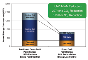
As shown in Figure 2, through the utilization of air recirculation and drying line controls, the new paint hangar will realize a 58% average annual energy reduction as compared to a traditional paint hangar design. Included in this energy savings is a 2,800 MCF per year reduction in natural gas usage and chill water energy savings of 326 MWh per year. As the greenhouse gas CO2 and smog-forming gas NOX are both products of energy generation, the reduction in energy usage will lead to a reduction of CO2 emissions of 227 tons per year and 313 lbm per year of NOX. These reductions in energy usage and environmental footprint are vital for achieving a sustainable paint finishing operation.
These examples of spray booth design strategies are simple illustrations of how proven automotive paint finishing design strategies can be applied to the design of an aerospace paint finishing facility to improve quality and sustainability. Beyond these examples, other technologies commonly used in automobile painting facilities, such as rotary applicators, robotic application and flexible conveyance systems, will become more and more prevalent within the aerospace paint finishing industry as aerospace manufacturers continue to look for proven methods to reduce operating costs, improve quality and increase throughput.


