
Conventional abatement technologies destroy the pollutants by heating up large quantities of air, and they are expensive to install and operate. As an alternative to the conventional abatement process, the “Fumes to Fuel” process concentrates the vapors and uses them in a fuel cell to generate a valuable byproduct: electricity. This article examines existing abatement technology, the new process and how it functions, the results associated with its performance, and the associated benefits.
Traditional Abatement Systems
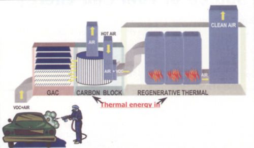
Current abatement systems in the automotive industry, as well as those used in other industries where VOCs are emitted, involve the “capture and burn” method. This method involves the direction of exhaust gas either directly to a thermal oxidizer or via a concentrator. In the present technology used at Ford Motor Company, spray booth exhaust is directed to a concentrator and subsequently a regenerative thermal oxidizer (see Fig. 1).
The concentrator consists of a section of stationary granular activated carbon (GAC) followed by a rotating drum containing carbon blocks. As the air passes through the GAC and rotating drum, VOCs are stripped from the airstream and adsorbed onto the carbon block. The clean air is then exhausted to the atmosphere. The rotating drum is separated into two zones. As the drum continuously rotates, the larger of the two zones is for adsorbtion of the VOCs and the smaller of the two zones is for desorption of the VOCs. Desorption of the VOCs is accomplished by heating air from outside and directing the heated air through the desorption zones causing the VOCs to become liberated from the carbon. The VOC-laden air is then directed to a regenerative thermal oxidizer for destruction through thermal degradation at >1,400°F. The use of the carbon concentrator has the benefit of reducing the amount of air sent to the regenerative thermal oxidizer by a factor of 10 while at the same time concentrating the VOCs to 10 times their original concentration.
The carbon wheel/regenerative thermal oxidizer system used at Ford Motor Company and other manufacturers is very effective at controlling VOCs. However, the system requires the introduction of millions of British Thermal Units of energy per hour in order to control the emissions. In addition, the concentrating capability is limited to 10:1 because the desorption gas is air, and safety requirements limit how close to the lower explosive limit the concentration of VOCs in the exhaust gas can reach.
An Alternative Abatement System
It was already recognized at the Ford Motor Company that there is energy in paint solvent. During the operation of our abatement systems, energy demand in the systems was slightly reduced (~15%) when VOC-laden air was introduced for control. Recognizing the fuel value of the VOCs as part of their work through the Energy Partnership, Detroit Edison approached Ford Motor Company with the idea of jointly developing a new abatement technology based on the use of the VOC as the fuel to drive an energy generator.
System Concept
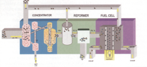
The system works in three stages (see Fig. 2). The first stage concentrates VOCs from the painting process, thereby increasing the fuel value of the gas stream entering the second stage. The second stage, called a reformer, converts VOCs into a hydrogen-rich mixture by breaking most, if not all, of the carbon bonds in the VOCs. The third stage is the fuel cell where hydrogen gas reacts chemically with air to create electricity, water, and a relatively small quantity of carbon dioxide.
This new approach required increasing the concentrating capabilities from 10:1 in air to 2,000:1 in a nonreactive carrier gas. To accomplish this, a new type of concentrator was required.
The fluidized bed concentrator was the equipment chosen to accomplish the increase in concentration capability. The fluidized bed concentrator differs from the carbon wheel concentrator in that the carbon is in the form of round beads of pure carbon whereas the carbon wheel uses a paper substrate impregnated with carbon fibers. The spherical shape of the carbon used in the fluidized bed allows for additional sites at which the VOCs can be adsorbed. This improves the concentration capabilities. In addition, desorption of the VOC has to be done with a nonreactive stream, such as nitrogen or other nonoxygen or chemically bonded oxygen-containing gas. This means that the concentration of VOCs can exceed the lower explosive limit because the oxygen normally found in air is not present.
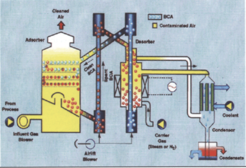
Figure 3 shows the concentrator equipped with a condensing unit. For many applications, the recovery of process solvent for reuse is very economical. For multicomponent solvents, similar to those used at Ford Motor Company, the chemical composition of the solvent is dependent upon the color painted at that moment in time. Therefore, recovery of the solvent for reuse is not available as the variability in the composition of the solvent makes its reuse uneconomical and a quality concern.
Environmental Comparison
To compare the emissions from the processes, an analysis of the emissions between the two systems was carried out (Table 1). For comparison purposes, a booth design exhausting 40,000 standard ft3/min to control was used.
| Traditional Abatement | Fumes to Fuel | |
| Thermal demand | 2,000,000 BTU/hr | 300,000 BTU/hr |
| Electrical | 48 kW (demand) | 0 (0–25 kW output) |
| NOx | 2,500 lb/yr | Negligible |
| CO2 | 800 tons/yr | 100 tons/yr |
| VOC | 10,000 lb/yr | 7,200 lb/yr |
The analysis shows that instead of the electrical demand associated with the traditional abatement equipment, the Fumes to Fuel system now produces more electricity than it uses to operate. In addition, NOx is virtually eliminated from the emissions and the remaining emissions are greatly reduced.
Field Testing of the Fluidized Bed Concentrator
The fluidized bed concentrator had been around for many years; however, its application to automotive surface coating had never been attempted. In order to determine its ability to handle VOCs from our painting operations, a test plan, utilizing the Design of Experiment tools of 6 Sigma, was developed that included various operating temperatures, solvent loading, and desorption flow rates.
In December 2002, Ford Motor Company conducted trials of the fluidized bed concentrator at the manufacturer’s facility located in Troy, NY. The testing was conducted using U.S. EPA test method 25a, calibrated with U.S. EPA protocol 1 propane calibration gas, on the inlet, outlet, and desorption sampling locations. Because the concentrations in the desorbate were higher than the normal operating range of the sampling equipment, a dilution probe system was used to dilute the sample to the operating range of the equipment.
The results of the testing showed that the concentrator works most effectively at 3 ft3/min of desorption flow rate. Removal efficiency test results at various temperatures are as shown in Table 2.
| Test Run | 350°F | 475°F | 600°F |
| Run 1 | 96.1% | 98.7% | 99.9% |
| Run 2 | 97.4% | 97.7% | 99.7% |
| Average | 96.8% | 98.2% | 99.8% |
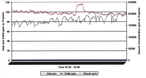
The testing conducted demonstrated that the fluidized bed concentrator could effectively remove VOCs from the air stream at levels consistent with Ford Motor Company requirements. In addition, the higher temperature desorption improved the removal efficiency. Figure 4 presents the inlet/outlet/desorption concentrations of the concentrator during one of the 600°F test runs.
Most important to note from Figure 4 is that, while the system was being loaded with approximately 100 ppm of VOC, the outlet concentrations remained near zero (the blue line at the base of the graph) and the desorber section was outputting between 150,000 and 200,000 ppm of VOCs (the new system may achieve as much as 3,500:1 concentration ratio). The testing confirmed the system’s ability to remove VOCs from the air, its primary goal, and provide high concentrations of VOC that could be used as fuel for an energy generating system.
Development of the Fuel Reformer
The energy generator chosen for this application was a Solid Oxide Fuel Cell. In order for the fuel cell to work, the VOCs had to be converted from their natural state into hydrogen and carbon monoxide. Ford Motor Company’s Scientific Research Laboratory (SRL) began working with suppliers to develop a fuel reformer capable of completely reducing the VOCs into usable products for the Solid Oxide Fuel Cell.
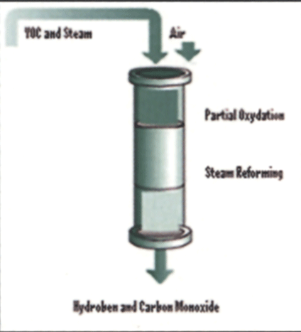
The first step was to determine a reformer strategy. The two options available were steam reforming and auto-thermal reforming. Steam reforming involves introducing the VOCs into a reactor vessel at high temperature (>800°C) in the presence of a catalyst. The temperature, combined with the steam and the catalyst, causes a disassociation of the molecular bonds. As a result of the disassociation, the hydrogen is liberated from the VOCs. The oxygen present in the water combines with the stray carbon atoms to form carbon monoxide. The major concern using this type of reformer is that the carbon to steam ratio needs to be very constant. In addition, the heat needed to maintain the reactor vessel at >800°C must be supplied from outside the system, requiring additional energy. If these ratios or temperatures deviate from expected values the system is prone to develop carbon buildup (coke). The deposition of coke inhibits the ability of the VOC to come into contact with the catalyst and acts as an insulator reducing the temperature at the reaction sites. Since Ford Motor Company VOCs are variable with the color of paint that is being applied, the risk of coking is relatively high. Given our desire for rapid development time and the risk of coking, another reformer strategy was chosen.
Auto-thermal reformation involves the introduction of a small amount of air into the reactor vessel. The oxygen from air, combined with heat, causes some of the incoming VOCs to combust. The exothermic (heat generating) reaction of combustion provides the necessary heat, in the presence of a catalyst and steam, to complete the reformation process through steam reforming. In addition, auto-thermal reformation is generally more tolerant of fuel variation and less susceptible to reduced conversion of VOCs.
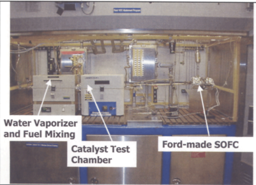
Figure 5 depicts a generic view of the reformation process used. Based on auto-thermal reformation as the reformer strategy, SRL began a series of laboratory experiments designed to develop the operating parameters necessary to deliver a high quality of hydrogen- and carbon-monoxide-rich fuel while completely destroying all the VOCs. To accomplish this, a test apparatus was built to feed a variety of VOCs into the reactor along with air and steam. The test apparatus is depicted in Figure 6.
VOCs in the exhaust stream from a Ford Motor Company paint shop can be categorized into four groups:
- Aromatics (i.e., xylene)
- Alcohols (i.e., n-butanol)
- Ketones (i.e., acetone)
- Esters (i.e., n-butyl acetate)
Using this apparatus, the team carried out a series of experiments using a variety of catalytic materials and a combination of the VOCs, identified above, over a wide range of operating conditions. The purpose of the testing was to determine the best catalyst and operating conditions necessary to convert all the VOCs into either hydrogen or carbon monoxide. While carbon monoxide is not necessary to run a fuel cell, the solid oxide fuel cell can use it, as with hydrogen, to generate electricity. Therefore, the carbon monoxide generated should be of good quality, which implies minimization of carbon dioxide content.
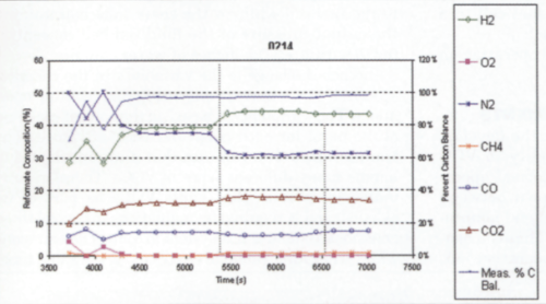
After numerous tests, SRL determined a catalyst material and the operating parameters necessary to convert all the VOCs into hydrogen or carbon monoxide. A sample of the conversion results is given in Figure 7.
The tests yielded a set of operating conditions that converted the VOC-rich stream into:
- 42% hydrogen
- 8% carbon monoxide
- 18% carbon dioxide
- 32% nitrogen
Based upon the operating conditions, a larger fuel reformer was built and tested.
Installation of the Equipment
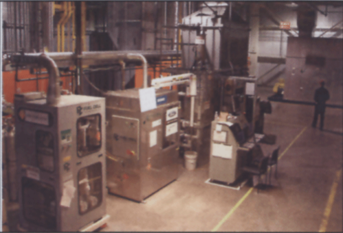
Once the equipment had been designed and tested, a program was begun to install the equipment into the Dearborn Assembly Plant Paint Shop. The installation location chosen was the process ductwork associated with the clearcoat painting operations. This process exhausts approximately 100,000 standard ft3 per minute of air/VOC from the automated sections of the clearcoat paint booths. This pilot system was designed to remove approximately 5% or 5,000 standard ft3 per minute of the clearcoat process air and treat it through the alternative abatement process. Installation began during the normal July plant shutdown and was completed prior to the plant startup. Figure 8 depicts the equipment as installed in the assembly plant.
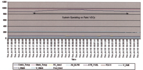
The equipment began operation on July 10, 2003. At the time of this installation, Ford Motor Company did not have a specification for receiving distributed generation. Therefore, a decision was made to output the power from the fuel cell to a bank of lights in the area of the fuel cell. A graph of the fuel cell system, while operating on VOCs, is presented in Figure 9.
Challenges and Accomplishments
One of the challenges encountered in the development of this system was the variability in VOC emissions from the process. During normal operation, the painting process is shut down between breaks, lunches, shift change, and weekend nonproduction periods. The solid oxide fuel cell has the benefit of tens of thousands of hours of operation but, because it is a high-temperature fuel cell made of ceramic type material, is intolerant of repetitive cooling and heating. Therefore, it was necessary to design the system to operate on both VOCs and natural gas. This gave the added benefit of being able to produce electricity for use in the plant even when the VOC generating process is not in operation.
Another of the challenges encountered was the extreme pressure differential between the output of the fluidized bed concentrator (around +2 inches of water column) and the inlet pressure of the alpha solid oxide fuel cell (around +60 psi). In the event that the pressure on the outlet of the fluidized bed concentrator exceeds 4 inches of water column, carbon bead material could be evacuated from the concentrator and deposited in the fuel reformer thus fouling the reformer. To solve this challenge, Ford and DTE engineers had to design a pressure control mechanism to regulate the pressure increase through the fuel reformer. The final control mechanism is capable of increasing the delivery pressure to the fuel cell while at the same time maintaining the output pressure of the fluidized bed concentrator to within ±0.5 inches of water column.
Another challenge is the variability in the chemical species of VOCs that are emitted during painting operations. This variability is based on the solvent make-up of the paint for each particular color of vehicle. The team designed a system such that it can be adapted to handle many different types of VOCs. Therefore, any industrial process that emits VOCs as part of its exhaust, and is required by regulations to control those emissions, could use this system to control its emissions while generating valuable electricity at the same time.
Conclusions
The team at Ford Motor Company has demonstrated the technical feasibility of converting VOCs into valuable fuel for a new generation of emission control devices. The alternative abatement system, also known as “Fumes to Fuel”, has begun the paradigm shift of thinking of VOCs as emissions that need to be controlled, into thinking of VOCs as a valuable resource that can be made to do useful work in the form of energy generation. This new technology provides a means to control VOC emissions from manufacturing operations at a substantially lower overall emission footprint. As the cost of fuel cells becomes more competitive with traditional electrical generation, the value of the VOC emissions makes the conversion of an energy demanding process into an energy generating process economically and environmentally attractive.
| The authors wish to acknowledge that this paper was presented at the Air & Waste Management Conference held in Indianapolis from June 21–24, 2004. We are grateful to the Association for permitting us to publish this paper. |
Contact the authors


