
Thickness variations are a reality in any plating and anodizing operation. Most specifications merely require that a minimum thickness be deposited on any given part.
Design engineers specific thicknesses for various reasons, including cost, function and decoration. (Cost will be discussed later.) Function minimums are required for a specific reason, such as the need to carry power, or, in the case of anodizing, wear resistance or the ability to absorb dye. Decorative thicknesses are usually selected for a specific effect. Base materials may be steel, aluminum, plastic, or copper or zinc alloys.
Dependant on the part size and shape, plating thickness will vary. The resulting differences may be as little as 0.1 mil in excess of thickness requirement, or they can be several times the minimum specified.
Take, for example, a component that is complex in design and includes recessed areas. Flat surfaces are easy to plate, but recessed areas present a challenge. The flat surfaces, and recesses create low and high current density zones, resulting in thicker or thinner plating on the same part. The component—a gear wheel, for example—may require a plating thickness of 1.5 mils overall, but on high current density areas, the thickness of the plated metal may exceed 8.0 mils. Even if the excess thickness doesn’t cause a problem, it nevertheless represents a waste of plating energy, time, raw material and costs money.
A flat part, such as a printed circuit board (PCB), has few recesses and usually much less plating thickness variation, but its design and shape present other problems. Plating thickness on trace heights, isolated component pads and blind holes on different areas of the part can vary so significantly that it creates functional problems with current carrying capability, impedance matching, solder mask application and the assembly of components.
Anyone who has been in the electroplating business for more than a few months is well aware that finishing metal parts costs money. It doesn’t matter what metal is being plated onto a given substrate. The situation is further complicated by the fact that most finishing specifications are open-ended. This means that the specs generally only require a minimum of plating or anodizing. This leaves the metal finishing shop with the question of how to manage costs.
Take MIL-G-45204 as an example of a specification. The spec requires 99.7% gold min and 0.00002 min thickness to satisfy the requirements of Type I, Class OO. Certainly, the plating shop can assure that the minimum thickness is applied to all surfaces, but it is not that simple. The problem is solvable by applying 0.0004” or 0.0005” gold. That should pretty well assure that the 0.0002” minimum is met everywhere but at what cost? The market price of gold is over “1700.00 an ounce, so adding twice the minimum costs big dollars.
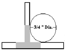
This might seem like an extreme example, but the same thing is true for every metal that is being plated. Even then, it is not that simple.THROW AND THE ¾ INCH RULEPlating uniformly into corners and other tight places is not just difficult; it is often not possible. Even where plating is deposited into recesses, it is generally much thinner in the recess or corner than it is on a flat surface. The plating typically thins in the final ¾ inch as the corner is approached. A thickness of 0.0002" at a distance of one inch from the corner may well result in 0.0000050" or less in the corner. Additionally, not all plating baths deposit with the same efficiency. “Throw” is the phenomenon of depositing or plating metals. The more difficult any metal throws, the more difficulty there will be in throwing into corners and recesses. In fact, many plating specifications include what is called the “¾ inch rule.” Simply stated, the rule says that the thickness requirements do not normally apply to any area of the part being plated that cannot be touched with a ¾ inch diameter ball, or the metric equivalent.
The formal definition of throw is, “the improvement of the coating (usually metal) distribution over the current distribution on an electrode (usually the cathode) in a given solution, under specific conditions.” The term is also used for anodic processes (anodizing) for which the definition is analogous.
In Figure 1, the area shown in gray will not plate as heavily as on flat surfaces. In this case, the ¾ inch rule applies. The corners are like a building protected by a lightning rod. The rod, or any sharp edge that can conduct the lightening to ground, attracts the electrical charges to metal so they do not harm the building. The same phenomenon results in less plating in the corners or other recesses. The result is called a “Faraday Cage.” In essence, the projections act very much like a lightning rod, drawing the current away from the tight inside corners.
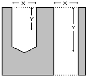
The same problem exists for holes (see Figure 2), both those going completely through the part and blind holes. Typically, plating will throw approximately 1 ½ times the diameter of the hole. Again, chrome is especially hard to throw into holes. Chrome may only throw ½ the diameter into the hole, while tin and zinc will throw slightly better that 1 ½ diameters.
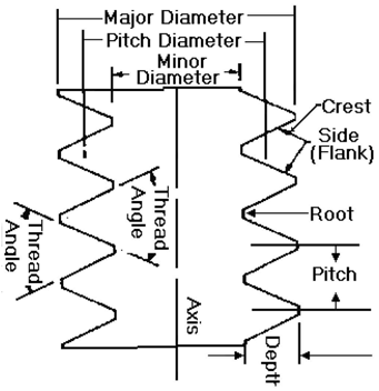
The problem is not without possible cure, however. The simple fact is, if the customer insists and is willing to pay the difference the parts can be plated using conforming anodes. This will commonly increase the plating cost by as much as 10 to 100 times the original cost, depending on the part topology and therefore seldom request it.THE RULE OF FOUR AND SIXAnother rule that affects not just plating cost but effectiveness as well is what is called “The Rule of Four and Six, found in many specs. The reader should understand that this is not a hard and fast rule supported by rigorous mathematics, but is rather an empirical rule, derived from experience or observation alone, without using scientific method or theory. Still, I have found this rule a good one to use when considering how much plating should be applied to external screws, bolts, and even hydraulic fittings.
Simply stated, the Rule of 4 and 6 says that the plating that is deposited on the major diameter of a screw or bolt will be about six times greater that that applied to the flat surface. Likewise, the plating applied to the pitch diameter will be four times that applied to the flat surface.
As a matter of fact, the thickness on the major and pitch diameters are not really arbitrary; rather, they are the result of how much plating is applied to flat areas of the screw, bolt, or even threaded fittings. The way to arrive at the desired thickness is to take into account the tolerance of the particular thread.
Given a tolerance of 0.0016" for a specific part the most that should be applied to the flat is .1667 % of the tolerance or 0.00026".Plating Concern for ThreadsSpecial considerations are necessary when using plating processes that add material thickness to screw threads. These processes include electroplating of zinc, chrome and cadmium as well as electroless nickel and many others. Processes such as black oxide coating, which transforms the surface but does not add significant thickness to the surface require no special attention.
Some authors write that plating will build up the thickness of an thread pitch diameter at as much as eight times the actual plating thickness. The major diameter will build up at two times the actual plating thickness (See Table 1). Another factor that complicates plating of threads is that some threaded parts are often very long and thin. Electroplating processes, because of higher electric currents at the ends of these parts, will deposit thicker coatings at the ends. A thickness of .0002 may be measured in the middle of a screw shaft while the ends measure .0004 on parts only 10 diameters in length. On longer parts, the difference can be even greater. If a screw and mating nut are both plated, fit-up problems can be expected.
One way to work around this build-up problem is to use special undersized, pre-plated thread sizes. This may be impractical, because, it can require special tooling and gauging.
Another consideration when evaluating plating is wear. The first level of wear on a plated part will be the plating itself. Once the plating has worn away, bare metal is exposed to the environment. Since Acme screws often “wear-in” much like plain bearings, bare metal can be exposed rather quickly depending upon the loading, duty cycle and lubrication present.
For very long parts, and parts in critical applications, use of stainless steel screws is often the best solution. No special sizing is required and after wear-in the exposed metal still provides corrosion protection for the application.
Coating thickness is an important variable that plays a role in product quality, process control, and cost control. Measurement of film thickness can be done with many different instruments. Understanding the equipment that is available for film thickness measurement and how to use it is useful to every coating operation.
| Plating Thickness | Major Diameter Increase | Pitch Diameter Increase |
| 0.00010.00020.00040.00050.00100.00200.0030 | 0.00020.00040.00080.00100.00200.00400.0060 | 0.00080.00160.00320.00400.00800.01600.0240 |
BIOLeslie W. Flott, Ph.B., CQE, ASQ Fellow, is certified as an IDEM Wastewater Treatment Operator and Indiana Wastewater Treatment Operator. He received his Bachelor of Science Degree in Chemistry from Northwestern University and his Masters Degree in materials engineering from Notre Dame University. Most recently, Flott served as the environmental program director and instructor at Ivy Tech Community College. Prior to that, he was the health, environment, and safety manager at Wayne Metal Protection Company.


