
While there are numerous ways of distributing power throughout an electrical system, selecting the most suitable option is typically determined by the operating environment, geometry, power requirements and cost. Following those same criteria, there are also multiple ways of providing adequate electrical insulation in order to protect not only manufacturers, service technicians and customers, but also expensive components that are in close proximity within an electrical system. One approach that offers significant advantages over a wide range of other applications is epoxy powder coating, which is effectively used as a high dielectric insulator on copper or aluminum conductors. Using the proper application method, virtually any configuration can be uniformly coated, ensuring a consistent insulation barrier. Due to its durability, epoxy powder coating negates concerns of cut-through or high-voltage spikes in cable insulations. Prototype and short-run requirements, in particular, benefit from using this insulation process, reducing the need for costly and time-consuming lamination fixtures typically required for multiple conductor assemblies. Powder coating technology has been in existence since the early 1950s and is recognized as a superior method of applying a protective finish on numerous shapes and sizes, as opposed to wet applications. Initially, this process was used predominately as an economical and consistent means of applying coatings to commercial consumables, with less regard to applications with electrical considerations. Over the years, advances in the application methods and powder chemistries have expanded the use of powder coating within the electrical field. Common applications now include motor components, switchgear and cable replacement, to name a few. Many powders used for these types of electrical insulation applications are rated as class B service coatings (266F/130C) and have a UL 94 V-0 flammability rating. The dielectric strength in certain powder formulations can consistently achieve 800v/mil based on the appropriate surface preparation, application method and component geometry. • Surface preparation – The surface requires a thorough cleaning and drying prior to the powder application. All contaminants must be removed to ensure proper adhesion. A phosphate solution and rinse is commonly used. There are a number of ways this can be accomplished, including spray wand applications, immersion systems or recirculating spray washers followed by a complete drying cycle.
In addition, edge conditioning is essential. The easing of sharp edges facilitates better material flow out and more consistent dielectric strength. The process used is in part dependent on the size and geometry of the component. Tumbling small parts is a common practice, while larger components require a manual de-burring operation. If applicable, raw material can be ordered with some radiused edges, eliminating a few secondary operations.
• Application method - There are a number of methods used to apply powder coating, each with their own attributes. Two of the most recognized are fluidized bed and electrostatic spray.
The fluidized bed process requires a pre-heat to the part. The part is then passed through a contained, suspended cloud of powder. The powder immediately adheres to the substrate and flows out. The last step in this process is a full cure in an oven. Dependent on time and temperature, powder thicknesses of at least 60mils can be achieved without geometrical concerns, although 20-25mils is most common.
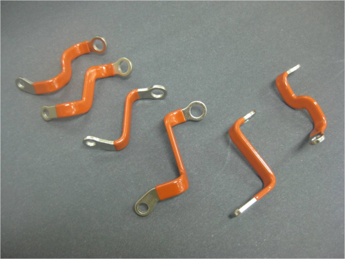
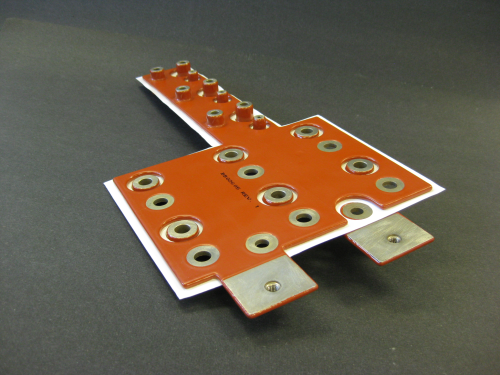
Electrostatic spray applications require a charged interaction between the substrate and powder. Parts are typically racked and grounded, then moved into a spray booth with the appropriate powder reclaim apparatus. The powder, stored in a hopper, is fed into an application sprayer that charges the powder to be deposited. Amperage, velocity and volume are all accurately controlled. There is no pre-heating required in this process if only 6-8 mils are needed. Thicker deposits, 10mils and higher, may require a pre-heating process. However, there are limitations to the thickness that can be uniformly deposited based on the part geometry and powder formulation. Upon completion of the spray process, parts are moved into an oven for curing • Component geometry – The size and shape of the component and desired dielectric strength can dictate the application method used to apply the powder. If a component is relatively flat or has an open geometry allowing powder to be evenly distributed, electrostatic spray is the preferred method. However, should the component have a tight geometry in which an electrostatic spray application would experience a Farady cage effect or back ionization and possibly require a thicker powder layer, a fluidized bed application is recommended. Space, thermal conditions, reliability and cost considerations continue to drive engineers to more efficient designs. The following are two applications in which powder coating should be considered: • Single conductor versus cable (See Figure 1) Taking advantage of a single copper or aluminum stamping, any geometric shape can be produced. Forming operations, if required, finalize the part configuration into one homogeneous component. This achieves tighter bends as opposed to cables that offer greater space utilization. By calculating the most appropriate width-to-thickness ratio needed for the required amperage, one can improve the airflow within the system. Elimination of crimped-on terminations reduces voltage drop and component count, which enhances reliability, especially in systems under heavy load or vibration. • Multiple conductor assemblies (See Figure 2) Applying the same principles as above, multiple conductor assemblies can be produced, minimizing the cost and lead time of laminated assemblies or a combination of both. Again, the operating environment and electrical performance may dictate the optimal construction method. There are three basic means of producing a multiple conductor powder coated assembly:
- The most simplistic is to powder coat each conductor and fasten them together with an epoxy resin adhesive or non-conductive fasteners. Either method will adequately secure the components together, offering installation of a single, modular assembly and reduced part count.
- An alternative approach is to adhere components together with a sheet of dielectric insulation with a thin film of double-sided adhesive. This material does not require heat activation and is therefore more sensitive to placement in the build process. It will however, improve the structural integrity and systems electrical performance.
- Lastly, masking the interior surfaces and adding a dielectric insulator between a typical two-conductor assembly will offer the optimal electrical performance. Eliminating the powder coating thickness between conductors and relying on the dielectric strength of the insulator will result in reduced inductance and increased capacitance. The closer the conductors, the better the results.
Design considerations. Engineers always consider how components interface with each other and their specific functions within an electrical system. This principle is equally important when specifying certain parameters on powder-coated parts.
Liberal tolerances on lines and circular masking locations will help reduce costs. Generally, masking is applied by hand using a high-temperature, pressure-sensitive tape wrapped around tabs or positioned over contact circles. A location range or not-to-exceed limit are preferred designations in mask positioning, allowing the operator and inspection more latitude. Scribing a line on the conductor will facilitate a more accurate mask location if necessary. Engineers should calculate dimensions to the base conductor prior to powder application. Then, specify the powder thickness range required. Avoid small cutouts if possible, as they are more difficult to edge, leading to potential test failure. A typical high potential electrical test can be performed if requested, scanning all surfaces at twice the operating voltage plus 1kV. The required test specification should be noted in the documentation. Using epoxy powder coating as a dielectric insulator is a proven and recommended technique for providing superior protection to electrical components. Powder coated conductors offer significant advantages in a system’s overall efficiency by providing improved airflow, space optimization and reliability along with reduced voltage drop and component count. Multi-level assemblies can be produced with quicker time to market and often lower cost. For the most efficient system optimization, discuss the referenced options with your application engineer.
BIO Robert Van Horn is the president of the Power Systems Division at Custom Electronics, Inc., a manufacturer of high-quality, high-reliability electronic products for military, commercial/industrial, renewable energy, aerospace and oil exploration markets. He is responsible for driving the development of new technologies and expanding the company’s capabilities in this growing market. Van Horn manages all engineering, sales and support programs associated with the Power Systems Division.