
A design of experiment (DoE) study was undertaken to identify the most important parameters to achieve high quality sintering and also choose the best electrode material to achieve this. The use of electro discharge sintering (EDS) to sinter iron powder and diamond into a segment and attach to a blade in a single step is also introduced.
Conventional manufacture of diamond tools involves mixing diamond grit and metal powder, and compacting in a mould. Porosity is then removed, forming a strong solid piece, by hot pressing in graphite or free sintering in an atmosphere controlled furnace. Alternatively, the porosity may be filled, as in infiltration, to form a solid. EDS is different in that a bank of capacitors is discharged thorough transformers, forming a single high caåurrent pulse which passes through the conductive powder under a compressive force. Sintering is believed to be accomplished by a combination of localised resistance heating and magnetic effects from the high current.
Experimental and production setup
All the experiments and production for this paper were performed on a Manfred Schlemmer, Model VVS 40/4 PC, computer controlled capacitor discharge welding machine. This equipment has a capacitor voltage of 3300V with an output voltage of 24V. The energy capacity of 38kJ is variable from 0 to 100% in 1% steps. A top-down hydraulic ram is used to apply force while sintering.
This ram has a maximum force of 80kN and a maximum ram speed of 400 mm/sec. The force of the ram is also adjustable from 0 to 80kN in 1kN steps. The transformers' ratios may be changed; the options being 200:1, 100:1 and 50:1. The 50:1 option is special to this particular machine. Changing from 200:1 to 50:1 reduces the current pulse duration while increasing the current pulse height. Metal powder is sintered by passing a high current pulse through the powder under a compressive force. Conductive punches are used along with a special mould which has an insulating insert to ensure current only flows through the powder. Initially, a form of Zirconia ceramicwas used, which was not ideal for this work. Later, silicon nitride (Si3N4) proved to be more suitable.
Producing EDS sintered segments
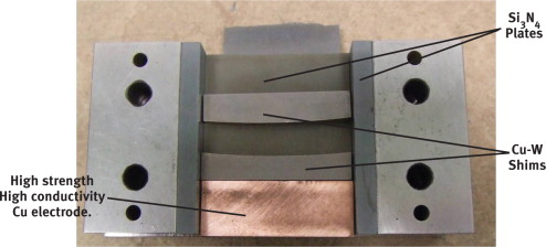
To examine the suitability of EDS in diamond tool production for a stone cutting application, segments (40mm × 3.4mm × 7mm) were made for a 400mm diameter blade and brazed to a saw blank to produce a tool. This was tested against a conventionally hot pressed tool. The mould used to sinter the segments is shown in Figure 1. It is a split design using tool steel as the main structure.
Within the steel are plates of silicon nitride as insulators, to ensure that all current flows through the powder. On the bottom and top are copper electrodes of high strength and high conductivity. Between these electrodes are shaped shims of copper infiltrated tungsten material (Cu-W). Without the Cu-W material, there is a greater chance that the Cu electrodes will weld to the sintered powder segment. The mould is assembled without the top copper electrode or top Cu-W shaped shim.
The mixture of diamond and iron powder is poured into the chamber and then the top Cu-W shim is inserted, followed by the top Cu electrode. It is important that the powder does not contain any organic material as the rapid sintering causes instant decomposition of any organics, which can be an explosive risk.
The assembly is placed in the welding machine and first pressed at 10kN to compress the powder without any current pulse. Next a 30% energy pulse at 27kN, followed by a second at 35%, is used to sinter the powder into a segment. By repeating sintering pulses, it has been found that densification can be achieved at lower force and energy.
Sintering experiments for the first segments
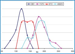
Iron powders were used from two manufacturers; Pometon of Italy (Feralloy DB1 & ST2) and Hoeganaes of Germany (Ancorsteel 737SH & 4600V). The Pometon powders are diffusion bonded while the Hoeganaes powders are pre-alloyed. The first segments made using raw ST2 powder were very soft and bent instead of breaking in the 3-point breakage test. To increase strength and hardness, powders were mixed with 0.8% carbon graphite by weight and heat treated at 750°C for 1 hour in a vacuum of better than 10−5 mbar. This improved the ST2 powder as average segment hardness increased from 100Hv to 130Hv.
The four powders were heat treated as described above and properties such as Vickers hardness and 3-point bend breakage strength measured. The two Hoeganaes powders achieved a higher average hardness of 170Hv–180Hv compared to 110Hv — 130Hv for the Pometon powders. Histograms of hardness measurements can be seen in Figure 2. For comparison, well-sintered standard bonds are expected to achieve the following Vickers hardness values:- NEXT100 — 250, NEXT900 — 200, HDR - 300 & CoEF — 260.
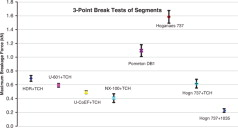
In the 3-point bend tests, all the standard bonds contain Elements Six TiC coated diamond product, SDBTCH, of grit size 4050 US#, at 16 concentration. These are all quite similar in strength. Both the 737 and DB1 which did not contain any diamond have much greater strengths. When the same diamond as in the standard bond segments is added to the segments made using 737SH iron, then the strength is reduced to that equivalent to the standard bonds. These results can be seen in Figure 3. When an uncoated weak grit (SDB1035) of the same size is added to the 737 iron segments, the strength is further reduced. This shows that the coating interacted and bonded with the iron during sintering.
Diffusion bonded Fe powders vs pre-alloyed Fe powders
In diffusion bonded powders, alloying additions are bonded to the surface of the powder. In conventional powder metallurgy sintering, at temperature with sufficient time, these additions can diffuse into the structure. In a pre-alloyed powder, any alloying additions are already alloyed within the powder so there is no requirement at temperature to diffuse the additions into the structure. EDS is such a quick sintering method, that pre-alloyed powders are more suitable because there is such little time for diffusion. This is clear from the hardness and breakage strength measurements of Figure 2 and Figure 3.
Granite cutting tests
Initially, a batch of soft segments, where the powder was not heat treated with carbon, was made using the 747SH iron powder and used to make a blade. While this did actually cut stone, the life was low. When this iron was hardened and another blade made, the life increased from 6.8m2/mm to 10.9m2/mm, or 60%. An average densification of about 95% of theoretical was measured for the segments. Both of these blades contained E6 SDBTCH coated diamond of size 4050 US# at a concentration of 16. These tests were done on Tarn granite class 3–4) at a depth of cut of 1cm and a head speed of 400cm/min, or a rate of 400cm2/min.
Head to head test against a standard hot pressed blade
For a direct comparison, the blade using hardened iron powder was tested head to head against a hot pressed blade using NEXT100 + 20Wt% iron. The work piece material was again Tarn granite. The cutting parameters were a depth of cut of 1.5cm with a head speed of 350cm/min, or a cutting rate of 525cm2/min. This would be considered a reasonably high cut rate for granite in industry. The test was continued until 2mm of segment height had been worn from the blades.
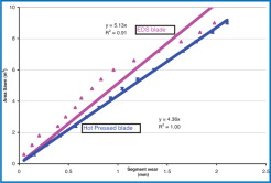
The two blades showed similar lives; 5.13m2/mm & 4.36m2/mm for the EDS and hot pressed blades respectively, as indicated by the trendlines. The respective lives as calculated from the final data are 4.67 m2/mm and 4.61 m2/mm. As can be seen from the deviation of the data points from the trend line in Figure 4, cutting using the EDS blade was somewhat less stable than the hot pressed blade, probably due to an inferior diamond distribution. It is also important to note that the EDS blade required notably higher power at the start of the test, again indicating that there could have been a greater number of working particles on the cutting surface when compared to the hot pressed blade.
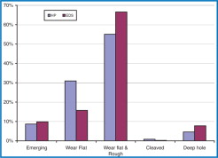
This difference in cutting was also visible in the particle analysis of the segment's cutting surface after the test. The hot pressed blade showed more wear flats than the EDS blade, which showed more rough particles. This would indicate that the EDS blade was being worked harder than the hot pressed blade. In conclusion, the two blades are well matched while the hot pressed blade could probably be pushed that bit harder. It could be inferred that the hot pressed blade has a wider operating window.
Design of experiment to investigate EDS sintering parameters
A design of experiment was used to investigate the most important parameters in the sintering of iron powder to a segment shape. The iron powder used was heat-treated 737SH. The factors investigated and the measured responses are shown in Table 1.
Table 1. Factors and responses for the design of experiment sintering investigation
|
Factor |
Low |
High |
Responses |
|
Energy (%) |
20 |
35 |
1) % densification from dimensions & weight 2) 3 pt bend test 3) Vickers hardness |
|
Pressing force (kN) |
20 |
30 |
|
|
Transformer ratio |
50 |
200 |
|
|
Mass of charge (g) |
6 |
9 |
|
|
Electrode material |
Cu |
Cu-W |
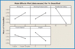
This matrix resulted in 32 samples being produced for testing. An in-depth analysis of this work is not possible here so a short synopsis will be given. All the main effects plots for each response look similar to that shown for the response “% densification”, as shown in Figure 6. There was no interaction worthy of note between the factors.
Conclusions for the EDS segment DoE
Having a transformer ratio of 50:1 is most important. This delivers the energy in a shorter pulse; in that the energy is dissipated quicker and at a higher current density. Using Cu as electrode material instead of Cu-W reduces the resistance in the circuit so that more energy is dissipated in the powder instead of the plungers. As much force as possible should be used when sintering, but not so much that the plungers are damaged. Obviously, more energy results in better sintering, but the correct amount of energy is needed for strength and densification. Too little and the sample will not be sintered, too much and voids can be formed, weakening the sample or welding the sample to the plunger. Again, it can be appreciated, that having less material to be sintered results in better sintering, for a given energy.
Using strip technology in the EDS sintering of iron segments
As described previously, when producing segments by EDS, the iron powder and diamond are mixed together and poured into the assembled steel mould shown in Figure 1. The opening is 3.4mm wide by 40mm long. Because no organics are permitted, it is difficult to attain a good distribution of the diamond in the segment as the diamond separates from the dry iron powder when poured. It will also be appreciated that as the steel mould is used, it becomes magnetised, which further complicates loading of the chamber as magnetic forces tend to hold the iron powder within the small opening. To avoid these problems, a strip of material about 0.5mm thick, containing the iron powder, diamond and carbon graphite, was made using E6 proprietary technology. The iron and diamond was the exact same as that used for the previous segments, tested in section 5.1.
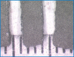
The strip was cut to fit the opening of the mould. These strip pieces were heat treated in vacuum (better than 10−5mbar) to remove the temporary binder in the strip, diffuse the carbon into the powder to harden and partially sinter to allow handling. An example of these strip pieces is shown in Figure 7. The manufacturing technology produces a strip with a good diamond distribution worked even at low concentrations, 16 in this case. Loading of the steel mould chamber now consisted of laying six pieces of strip in the chamber instead of pouring a mixture of diamond and powder. Segments were made with these strips, using the same EDS parameters as described in section 4, and a blade manufactured from these segments. The sintering of these segments was sufficiently good that when looking at the fracture surface of a broken segment, it is not possible to discriminate between each piece of strip.
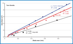
This blade was also tested on Tarn granite at 1cm depth of cut and 400 cm/min head speed, along with the EDS powder blade as used previously. To test the potential of this strip blade, a test at 600cm2/min cut rate was also performed by increasing the depth of cut to 1.5cm. The results are shown in Figure 8. This graph shows that there is only a small difference between the segments produced from strip and those produced by mixed powder and diamond at 400cm2/min. In addition, the strip was capable of being used at a 50% higher cut rate (600cm2/min), all be it with a reduced life.
Sintering iron powder to a dense solid
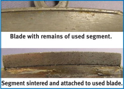
With control of sintering parameters and mould design/materials, it is possible to sinter the powder-diamond mixture to a strong solid and attach to the blade blank or used blade in a single operating step. To show this, a used blade was cut into pieces which had the remains of a segment still attached, as shown in Figure 9.
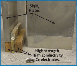
For these tests, the mould design had to be modified to take into account the fact that the blade was thinner than the finished segment. The two larger Si3N4 plates were remanufactured to tightly grip the blade while leaving an opening for the segment above the blade. An example is shown on the right of Figure 10. Current was to pass through the top punch and W-Cu shim, then the powder, and then the blade piece to sinter and attach the powder as a solid to the blade. This did not work, as the blade piece conductivity is too low and frequently welded to the copper welder base. Also, the iron powder did not sinter well.
To be able to do this successfully, copper conductors had to be pressed tightly against the blade piece, instead of the Si3N4, allowing the current to pass from the powder, through the minimum of blade material and then directly into high strength high conductivity copper which sat on the copper base of the welder. This is shown in Figure 10. The iron powder-diamond mixture was sintered by pressing at 27kN and using double pulses of 35% energy. Using this method, segments were successfully sintered to a strong solid and attached to the worn portion of an old segment on the blade, as shown in Figure 9.
To test the bonding strength, the blade pieces were held horizontally and the sintered segment pushed off while measuring the force on an Instron. Push off strengths of between 3 and 4 kN were recorded, which are considered to be sufficient for a 400mm sawblade. Failure was at the bonding between sintered iron segment and the segment remains on the blade.
Conclusions
- It has been shown that a diamond saw blade can be made by EDS sintering segments using standard iron as bond material;
- EDS segments showed a hardness approaching that of conventional segments and breakage strength equal to conventional segments; Adding 0.8 Wt% carbon and heat treating improves the hardness and strength of the segments;
- Average densifications of about 95% were measured for the segments;
- In reasonably aggressive granite cutting tests, the EDS blade can equal a high quality conventionally hot pressed saw blade in terms of cutting life;
- DoE analysis showed that the transformer ratio was the most important factor controlling sintering quality. Using high conductivity electrodes, higher energy and pressing force all improve sintering quality;
- Segments made using strip instead of a mixture of diamond and iron powder also worked successfully in stone cutting;
- It has been shown that a diamond and iron powder mixture can be sintered to a solid and attached to a worn tool in a single step and held there with sufficient strength for stone cutting applications;
- and in the future, it would be very interesting to test this sintering & attachment technology in the manufacture of a complete blade, and then compare the performance to that of standard production blades.
The authors
This paper written by David Egan and Seamus Melody of Element Six Ltd., Shannon Airport, Shannon, Co. Clare, Republic of Ireland. It was presented at EuroPM 2008 in Mannheim, Germany, and is published with permission from the European Powder Metallurgy Association.


