
Direct metal laser sintering (DMLS) produces solid metal parts by locally melting and solidifying metal powder with a focused laser beam, layer by layer. A 3D computer-aided design model is “sliced” into layers, and the lasersintering technology then builds the geometry. The technology’s Munich based manufacturer, EOS, says that it can create extremely complex metal parts in a relatively short cycle time and is particularly suitable for industries that no longer need to produce a large volume of identical parts.
Potential applications cited by EOS include tooling, aerospace and automotive industries, designer objects, consumer goods such as toys, and robotics. New applications are being found in the medical field – dental prostheses, implants and devices. According to the EOS website: “Laser-sintering enables a rethinking in product development and production. It is a departure from tool-based, inflexible technologies in favour of generative, flexible methods.” Claudia Jordan, an EOS spokesperson, said: “The most groundbreaking aspect of the technology, in our opinion, is freedom of design. This makes it possible to produce really attractive products, such as customised implants and lightweight structures for aerospace and professional cycling.”
But is the technology – also called e-manufacturing by the company – an innovation too far for customers in the current economic climate, where innovation can take second place to the stability of “traditional” technology?
One user of the technology is LBC Laserbearbeitungscenter GmbH, a manufacturer of inserts, parts and prototypes for diecasting and injection moulding. Currently, 20% of its work involves producing prototypes for aircraft, the medical industry or for the automotive sector. It was established in October 2002 and only two years later started using EOS’s DMLS technology. In the injection moulding tooling business, there is hardnosed business reasoning behind the deployment of innovative technology. The DMLS system allows LBC to build moulds that include internal conformal cooling channels. These are carefully calculated and designed to reduce the time taken to cool the mould in each moulding cycle, making for faster throughput and improving productivity and, therefore, profitability. “We’re very pleased with the technology. It is excellent for mass production moulds,” said Ralph Mayer, managing director of LBC. “With conformal cooling we can achieve cycle time reduction up to 60%, although the average time reduction is 30% to 40%.”
Conformal cooling is, in fact, a fairly recent commercial reality. “In theory, EOS has been dealing with the concept of conformal cooling for over 10 years,” said Jordan. “But it was only when we started to implement MS1 (a maraging steel in fine powder form) at the end of 2006 that EOS could actively offer conformal cooling.”
DMLS allows for almost any shape in heating/cooling channels and thus can already improve the effectiveness of cooling. However, by using conformal cooling with DMLS, routing options for cooling channels are almost infinite. EOS goes so far as to claim that certain geometries of products can only be manufactured at required quality standards with conformal cooling. “It is suitable for making very complicated parts to a very high quality in a much faster time than traditional moulding,” agrees Mayer. “For example, a gear wheel requires special milling tools to be created, and can take up to four months using existing technology. Using DMLS, it is possible to make a prototype in just one week.”
Benefits of conformal cooling
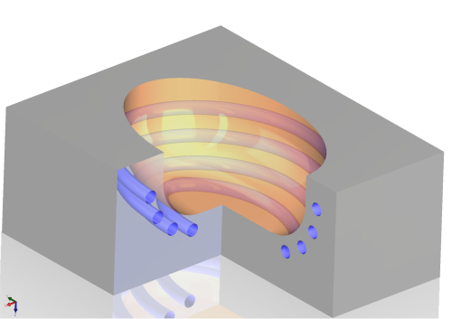
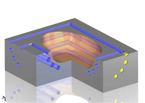
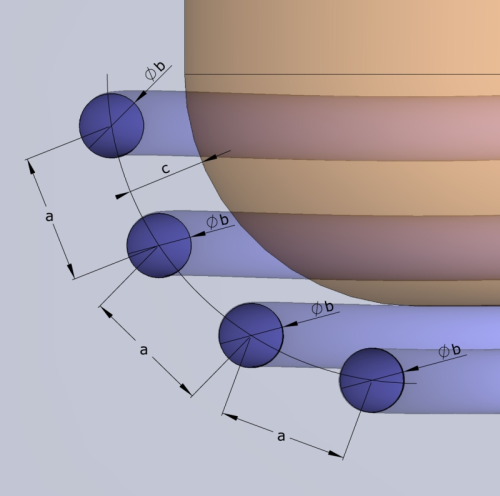
According to an EOS white paper, conformal cooling works by creating a suitable cooling channel at a well defined distance to the cavity, which is impossible using a conventional drilled cooling mechanism (Figure 1). Cooling channel cross sections can take almost any shape. Turbulence of the coolant (the desired high Reynolds number) within the system can thus be controlled by actively choosing different cross sections and by switching between different cross sections. As a consequence, turbulence inside the coolant stream is generated close to the mould cavity along the whole path of the channels. Changing the cross sections or forking the cooling channel can be done without splitting up the form. This allows for additional heat/cooling advantages in areas that cannot be reached by conventional methods.
Conformal cooling can also improve quality due to better control of the injection moulding process. Warping and sink marks are minimised by evenly cooling out the plastic melt, thus minimising internal stress. Scrap rates are reduced or eliminated. Avoiding internal stresses helps to produce better parts with the same amount of required material. In fact, certain geometries are only possible to manufacture at required quality standards with conformal cooling, EOS says.
Combined systems with separated cooling and heating channels are also possible, and the technology can also perform a split between main systems (for the control of the global temperature) and specific systems (for the handling of close to cavity critical temperatures), opening up the potential for future applications.
Heating/cooling at critical parts inside the tool, which often cannot be reached by conventional methods, becomes feasible (eg long and lean cores, areas around hot-runners or small sliders). Using special copper heat conductors or other complex measures becomes obsolete. If necessary, it is also possible to undercool mould cavities, thus reaching optimal cycle times by minimising cool down times in tooling cavities. An evened out temperature level can help to improve tool life time. This becomes relevant especially in die casting tools that are exposed to extreme temperature variations. In the white paper, EOS also sets out the drawbacks of conventional cooling. The distance from cavity to cooling channel differs, as only straight line drilling channels are possible and as a consequence heat dissipation cannot take place uniformly in the material.
This can result in uneven temperature levels on the cavity surface, uneven cooling-down processes resulting in internal stresses and thus negative impact on part quality (warpage). The drilling procedure is not without risk: in the case of deep drilling there is always a danger of hitting ejector holes (wandering drill), or the drill can even break. As a consequence, the whole mould insert could become unusable.
In conventional cooling, optimising the cooling channels helps condition the tooling temperature, enabling uniformity. This temperature level can be influenced to achieve on the one hand a lower temperature for quicker cooling, or higher temperature for better product surface quality on the other. Conventional cooling channels are drilled into a tool. This limits design to straight lines, easily accessible by a drill. Tooling cavities can pose limits to position and outing of conventional cooling channels. With DMLS, however, the cooling channels can be positioned freely. The cross sections can be optimised to mould temperature control requirements.
Future developments
Some of the results already obtained by using DMLS to create injection moulds and mould inserts with conformal cooling include a 20% increase in mould productivity and a 50-hour toolmaking time for a blow-mould (Es-Tec), reduced cycle times from 15 to 9 seconds, enabling a 75% increase in productivity on a four-bottle blow mould with DMLS inserts (SIG Blowtec) and reduced cycle time by two-thirds using a DMLS designed core effectively cooling down a critical hot spot (LaserBearbeitungsCenter).
EOS says that DMLS can make electric discharge machining (EDM) and milling obsolete in many cases, especially with part geometries where slides, inserts or other tool components with complex characteristics are required. But one issue with the technology is that building rate is still a problem, according to Mayer. “Currently it is much faster to build components in large numbers using traditional moulding technology. At the moment, using DMLS, we can only produce 8cm3 per hour. However it seems likely that this will improve in the future.”
One way to get around this, he says, is to combine DMLS with traditional technology and use it to complete manufactured tools by adding the complex exterior parts. LBC updated their technology 2006 when the company bought a batch of newly updated machines from EOS. So how have things improved in the last few years? “Since 2004 we’ve found that building accuracy and surface quality has improved and it is now possible to use a greater range of metals,” says Mayer.” We generally used steel 1.2709 or stainless steel for inserts but it is likely that aluminium, titanium and other steel grades will be used in future, provided that their carbon content is relatively low.”
“Recently we have been able to use new materials matching properties and materials already known, such as cobalt-chrome, titanium, and maraging steel,” adds Jordan. “There have also been software updates. The development of parts for the dental industry is a new innovation.”
But how will the technology fare in an economic slowdown? “One economic benefit is that customer demands can be quickly adapted to. In the case of insecure demand forecasts, tools can be omitted and plastic parts can be made directly with plastics laser-sintering. In this way, the labour cost share of total costs is less and material can be saved,” says Jordan.
“In the future we anticipate interest from all markets that combine complex product designs with an urge to adapt to individual customer demands (such as aerospace, medical implants, special purpose equipment, tooling, etc.) We plan to continue to develop the technology for dedicated applications.”
Worldwide expansion could also be on the cards. Due to disputes with 3D Systems, EOS has only been able to distribute DMLS technology in the US for the last four or five years. The first purchaser of the technology was Morris Technologies Inc (MTI) is a rapid prototyping company. In May 2009, the company bought its ninth machine, an EOSINT M 270 system for laser sintering titanium. “We were the first US firm to install DMLS equipment,” says Greg Morris, CEO/COO of MTI, “and yearly demand for laser-sintering services has increased. We expect interest in titanium parts to follow the same strong demand curve.”
End users are sometimes initially wary of the product, however. “We did have some trouble persuading our customers of the benefits of the technology at first. It sounds very strange at first – like something out of science fiction – and some found it hard to believe it could actually work. Another customer issue was the consistency of the finished metal. Many didn’t think that metal powder could create the same consistency as ordinary solid metal, such as rolling mill steel,” Mayer says. “In fact, using metal powder ensures that the material is finally more consistent and has the same specifications throughout.” Jordan agrees. “A lot of clients were suspicious of the technology in the beginning because at that point in time they haven’t heard about the technology before and as such did not know the advantages,” she says. “We needed to convince them. We did this by showing off the scope of this technology through illustrative benchmarks. Customers use these benchmarks in their manufacturing processes and experience the advantages hands-on.”
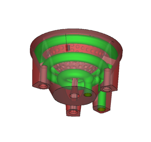
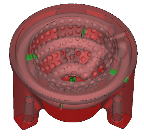
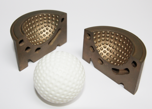
Case study – golf ball
In this example, DMLS technology was used to make a give-away golf ball to be produced in large quantities at low costs, Blow moulding extruded polypropylene (PP) combined with the injection of an elastomer was required. Usually the main challenge with this kind of form is venting the tool which can, in the worst case, lead to deformed golf balls. The solution was to integrate venting channels with almost invisible openings near the cavity.
Due to the choice of the process parameters, the pressure could escape and but the channels did not clog up. The volume of the cavities could be minimised, which helped reduce building time and thus the costs of the DMLS tool. Eight cavities were combined, making up for a four cavity tool, producing more than 20 million golf balls. Building the tool took only 50 hours, and conformal cooling channels increased productivity by 20%.
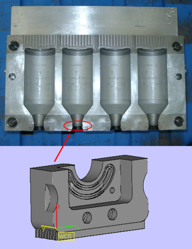
Case study – PE bottles
In this case study small DirectTool inserts with conformal cooling channels were built and integrated into a conventionally manufactured tool in order to extract the heat from these parts more quickly. The inserts reduced cycle times from 15 down to 9 seconds. This enables a 75 % increase in productivity for a 4 bottle blow mould without sacrificing on quality. The cycle-time and productivity of this type of tool were limited by the time it took to cool down the bottle necks as wall thickness reaches a maximum there. Figure 5 shows three examples using conformal cooling channels. Figure 5a shows a tool for blow-moulding PE bottles, while figure 5b shows a cooling pin for cooling an injection point – a classical hot spot. Conformal cooling in this case reduces cycle times by two thirds. Figure 5c depicts a core with spiral conformal cooling channels inside the dome. By conventionally milling the lower part of the tool and limiting DMLS to the part with conformal cooling, costs were reduced. A 0.3mm machining allowance was added for finishmachining of the outer surface.
In this case, the preferred design does not require a new channel layout. In this example two ejectors are bypassed in the space between without pushing the remaining wall thickness to a critical limit. The cross section area along the channel has to be kept constant, to avoid flow braking effects.


