

The market for advanced ceramic products is growing continuously. The reason lies in the unique property profile offered by ceramic materials. Ceramics are the material of choice for applications under extreme conditions such as high temperatures, corrosive atmospheres, abrasive conditions, or high loads at high temperatures. Ceramics combine excellent mechanical properties with low specific weight. This combination makes them interesting as light-weight construction materials for moving components in automotive, aerospace applications and for engine components [1].
Two-component ceramic injection moulding allows the combination of materials with different properties for a high throughput, net-shape production of multifunctional parts. The challenge of this shaping technology is adjusting the shrinkage of both components during injection moulding, co-debinding and co-sintering.
The materials chosen for the combination must have comparable thermal expansion coefficients and similar sintering behaviour. Fourteen partners from seven European countries have developed ceramic components for automotive and railway applications by two-component low pressure (2C-LCIM) and high pressure ceramic injection moulding (2C-CIM) within the framework of a European project. Part of that work, reported here, was carried out at the Fraunhofer Institute for Ceramic Technologies and Systems (IKTS) in Dresden.
The results of the project were parts with complex geometry consisting of two ceramic materials with different mechanical, electrical or tribological properties like a ceramic glow plug for diesel engines, a gear wheel for fuel pumps, a valve seat and braking pads for high-speed train brakes.
However, the role of advanced ceramics in engineering structures largely depends on the market driver of reliable mass production of complex-shaped components at acceptably low costs. Because of near-net-shape products and the economic efficiency inherent in large series production powder injection moulding (PIM) is the preferred shaping technique for metal/ceramic parts of complex geometry [2]. The process is capable of providing not only shape complexity but also high precision and high performance properties in the sintered parts [3].
Tolerances of down to 0.3% or better are generally claimed by PIM producers. Injection moulding offers the advantage of making ceramic parts with internal or external gears, undercuts, hollows, cross holes, and serrations without any subsequent time- and cost-consuming mechanical treatments [4].
First research results have shown that ceramic materials can be combined in one part by two-component ceramic injection moulding [5], [6] and [7] and a number of model systems have been produced. These include (1) a component with alumina skin and core, possessing a 0.5 μm particle size skin layer surrounding a 1μm particulate core [5]; (2) toughened components with a skin containing 20 vol% partially stabilised zirconia surrounding a 100% alumina core [6], and (3) a ceramic heater consisting of different Al2O3/TiN-mixed ceramics [7]. The combination of different ceramic materials and ceramics with metals by two-component injection moulding is described in [8].
Within the European specific targeted research project (STREP) “CarCIM” set up under Framework 6 funding, 14 partners drawn from industry and research groups across seven European countries developed ceramic components for automotive and railway applications by two-component ceramic injection moulding (2C-CIM).
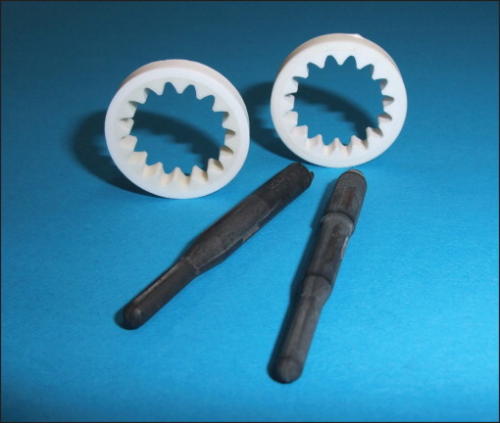
The project resulted in four 2C-CIM prototype parts integrated in systems for functional testing and verification through techno-economic assessment of the complete processing chains that were developed in four parallel case studies: (1) ceramic glow plug, (2) ceramic gear wheel, (3) ceramic valve seat, and (4) ceramic braking pads for high-speed trains [9]. The development of the glow plug by two-component low pressure injection moulding (2C-LCIM) and the development of the gear wheel as an example for the combination of a hard and a tough ceramic material are described in this contribution in more detail (Figure 1).
The insulating and the conducting phases of the glow plug were made by mixtures of silicon nitride powder (Si3N4), Silzot HQ (H C Starck, Germany) and UBE E10 (UBE Europe GmbH, Germany) with certain amounts of molybdenum disilicide (MoSi2), Grade C (H C Starck, Germany). Mixing of the initial powders was carried out in isopropanol in an agitator ball mill. The dispersion medium was removed in a spray drier afterwards.
For the gear wheel, alumina as a very hard and wear resistant material for the inner gear ring had to be combined with zirconia-toughened alumina for the outer ring. Alumina (CT3000SG, Almatis, Germany) and ZTA (alumina CT3000SG, Almatis, Germany with 7 wt% 3YSZ40, Degussa-Evonik, Germany) were used for manufacturing the prototype parts of the gear wheel.
The feedstocks for 2C-LCIM were prepared at 90°C in a solvent based on paraffin (H&R Wax Company) and bees wax (Merck) after annealing the powders at 120°C. To adjust the shrinkage of both components of the glow plug the solid content of the feedstocks had been varied between 81.5 and 85.5 wt%. All feedstocks were characterised by their viscosity by means of a rotary rheometer using a plate-plate measuring device (Physica GmbH, Germany).
The preparation of the high-pressure injection moulding feedstocks was accomplished on a shear roller (BSW 135-1000, Bellaform, Germany). Before starting the compounding process the powders had been dried in a cabinet drier at 120°C for at least 12 hours to remove adsorbed water from the surface. A mixture of the commercially available binder Licomont® EK 583 (Clariant, Germany), Mirathen®, a polyethylene compound (Dow Plastics, U.S.) and stearic acid (Merck, Germany) was used as a binder. The solid loadings of the feedstocks were 55 vol% in case of the material combination Al2O3/ZTA.
Two-component testing bars (5 × 5 × 70 mm3) were initially injection moulded to develop a co-debinding and co-sintering procedure for the glow plug component. The interface between the conductive and the insulating phase was investigated by FESEM and optical microscopy. Single-component bars were produced for testing the thermal and mechanical properties of both materials. The two-component prototype tool for glow plug production was made by Hidria AET doo, Slovenia. Low-pressure injection moulding was carried out at a temperature of 115°C and an injection pressure of 0.5–0.6 MPa by means of a low-pressure injection moulding machine (SOMTEC GmbH, Germany). The conductive part of the glow plug was injection moulded as the first step. To complete the glow plug with the second component the tool had to be converted and the conductive part was inserted in the tool again. Now the insulating component was injected.
A round robin testing tool for investigating the feasibility of two-component injection moulding parts from all high-pressure feedstock combinations developed in the European project such as the prototype tool for high pressure two-component injection moulding of the gear wheel was designed by Fotec GmbH, Austria and constructed by Ernst Wittner GmbH, Austria. The round robin testing tool was provided with four cavities, two of them for shaping of simple cylindrical two-component parts and two for manufacturing cylindrical parts with a ring-shaped second component on the top. The prototype tool for the gear wheel was a two-component tool using rotary-plate-technology. In the nozzle side there were two cavities assigned to the inner and outer ring of the gear wheel. At first the inner ring was moulded by the horizontal injection unit. While the sprue was ejected from the opened mould the first component stayed on the core and was transferred to the second cavity by tool rotation. The second feedstock was injected by the vertical injection unit. Since both injections were performed simultaneously at each tool opening one two-component part was produced. An Arburg 320S machine was used for two-component injection moulding.
Co-debinding profiles were calculated by Robert Bosch GmbH for both low- and high-pressure parts. Mass loss rates during thermal treatment were calculated by applying formal kinetic analysis of the decomposition behaviour constant.
The low-pressure injection moulded parts were debound in nitrogen up to 700°C. In comparison to the conventional debinding path this novel route, derived from formal kinetic analysis, could be shortened to one quarter of the original debinding time. Additionally, complete embedding of the components during debinding could be omitted. The parts were only positioned on a powder bed for support during the binder removal by the wicking effect of the fine-grained powder.
Co-debinding of the gear wheel prototypes was carried out in air up to 450°C. The debinding time could be reduced by 40% using the calculated optimised co-debinding route.
The glow plugs were sintered at 1750°C under nitrogen gas pressure, whereas co-sintering of the gear wheels had been carried out at 1620°C for four hours in air.
X-ray computed tomography was used in the green, the white and in the sintered state to detect and investigate any defects in the two-component prototype parts. The CT investigations were carried out using a “CT-Compact” tomograph constructed by PROCON X-Ray/Germany and the Fraunhofer Development Centre for X-Ray Technique Fürth/Germany. It is a 3D-X-ray device equipped with a 150 kV microfocus radiator with a radiation power of 75 W and 750 mm distance between focal spot and detector. The flat panel detector allows a resolution down to 21μm.
The co-sintering process of the gear wheel was investigated by optical dilatometry by Robert Bosch GmbH. Deviation from the geometry demanded of the components was measured by a 3D co-ordinate measuring technique.
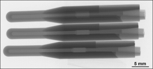
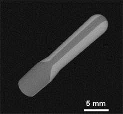
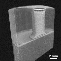
The results of the feasibility studies with simply shaped two-component bars of the low pressure injection moulded feedstock combination of electrical conductive and insulating ceramic materials showed that the materials can be combined by this technique. Adjusting the total shrinkage of both materials via the solid content of the feedstocks was essential for achieving defect-free co-debound and co-sintered parts. Figure 2 shows radiographic images of three prototype parts of the glow plug in the green state without defects. An impression of the three-dimensional shape of the tip of a glow plug is given in Figure 3. Testing of sintered glow plugs demonstrated that with a voltage of 13V a tip temperature of 1230°C could be reached within an ignition time of three seconds.
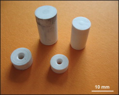
Figure 4 shows testing parts achieved with the round robin testing tool in the green and in the sintered state. These tests demonstrated the feasibility of high pressure two-component injection moulding of the different feedstock couples used in the project in principle, but on the other hand they also emphasised the challenges of this shaping technology. In Figure 5 it can be seen that cooling stresses between both components in the injection moulding tool caused a crack initiation in the interface between the first and the ring-like second component.
The cylindrical geometry of the testing part proved to be difficult for injection moulding due to jetting effects and for debinding, too. The two-component injection moulding technique had been applied to the manufacturing of the testing parts in such a way that the first component was inserted in the tool again for injecting the second component. This procedural method turned out to be disadvantageous for achieving defect-free parts because separated binder accumulated in the interface and caused failure in debinding.
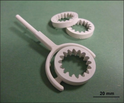
The components consisting of alumina/ZTA produced with the prototype tool are shown in Figure 6.
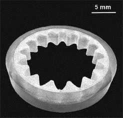
In spite of the fact that alumina starts to sinter at slightly lower temperatures than ZTA both components could be sintered to defect-free parts. The sintering behaviour at 1100°C and at 1600°C, respectively, can be seen in Figure 7. To avoid critical thermal stresses during cooling of the co-sintered ceramic part the thermal expansion coefficients of both ceramic materials must be quite similar. The computed tomographic reconstruction image of a sintered gear wheel in Figure 8 shows that these prototypes could be achieved without any defects. However, 3D co-ordinate measurements emphasised a slight deviation of the parts from roundness. The reason for this deviation can be seen in a slightly different density distribution in the green parts in the regions near the sprues and near the weld lines which form perpendicular to the sprues. Torque measurements carried out by Robert Bosch GmbH on sintered parts demonstrated that the ceramic gear wheels can resist a torque > 1 Nm which is demanded in the specifications of the component.
Acknowledgement
The CarCIM project was funded by the European Commission within the 6th Framework Programme (TST5-CT-2006-031462). For references, contact the author.

